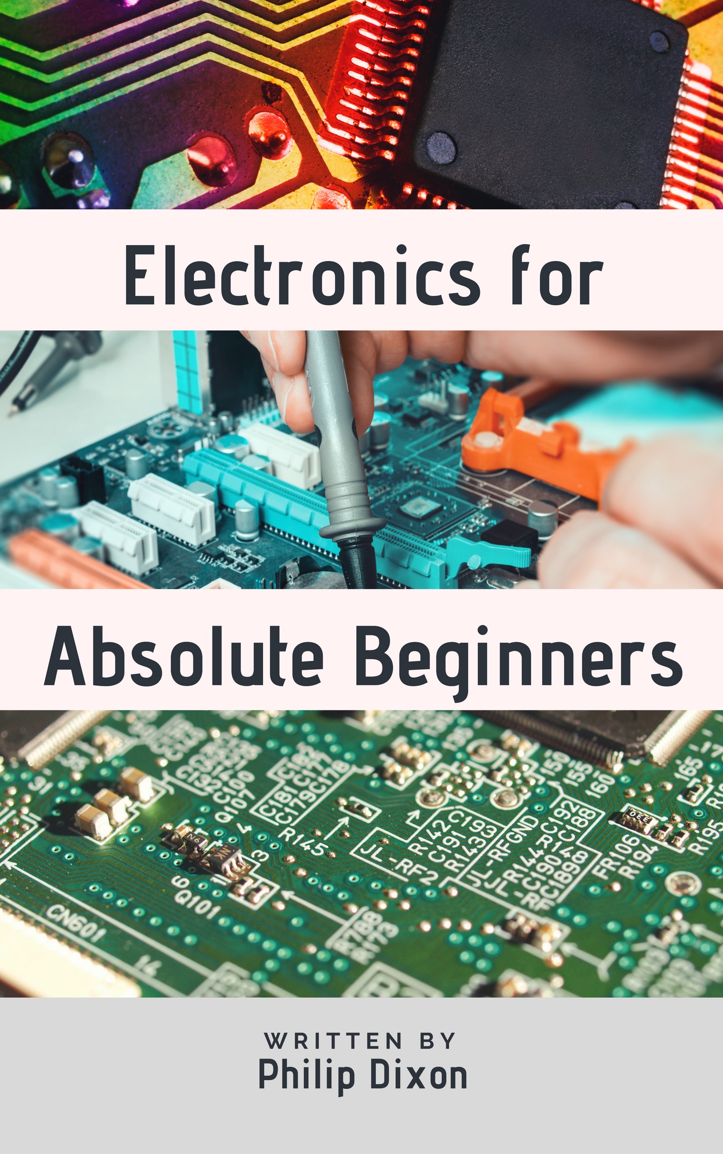
Electronics for Absolute Beginners

Quickly get up to speed in the exciting world of electronics.
You can buy the Electronics for Absolute Beginners book (as an eBook or paperback) from the following Amazon sites:

|
Amazon.com |

|
Amazon.co.uk |

|
Amazon.ca |

|
Amazon.de |

|
Amazon.in |

|
Amazon.fr |

|
Amazon.es |

|
Amazon.it |

|
Amazon.nl |

|
Amazon.co.jp |

|
Amazon.com.br |

|
Amazon.com.mx |

|
Amazon.com.au | ||
Electronics Videos
All our videos are designed to be easy to follow, interesting (hopefully) and educational. Aimed at people new to electronics who want to learn the basics, but perhaps would rather watch a video than read a book.
Build a Bistable (Flip-Flop) 555 Timer Breadboard Circuit
A bistable, or flip-flop circuit, is a circuit that is stable in two states.
Whether the output is high or low is determined by two push buttons: S1 and S2. When S1 is pressed, the output goes high and the LED is switched on. It stays in this state until S2 is pressed, which sends the output low and switches off the LED.
Flip-flops are simple memory circuits that are cable of storing a single bit of data, which can be either High (On or 1) or Low (Off or 0). Flip-flops can be combined to create registers, which in turn can be used to store data or the results of calculations in devices such as microcontrollers.
Build an OR Gate Breadboard Circuit Using Two NPN Transistors
With an OR Gate, the output is "True" when either input is "True", or when both inputs are "True".
This simple breadboard circuit shows how to create an OR Gate by using two BC547 NPN (BJT) transistors.
Initially, the LED is not illuminated, and remains that way until either (or both) buttons are pressed.
Build an AND Gate Breadboard Circuit Using Two NPN Transistors
With an AND Gate, the only time the output is "True" is when both inputs are "True".
This simple breadboard circuit shows how to create an AND Gate by using two BC547 NPN (BJT) transistors.
Initially, the LED is not illuminated, and remains that way until both buttons are pressed.
Build a NOT Gate Breadboard Circuit Using an NPN Transistor
A NOT Gate, which is also known as an "Inverter", produces an output that is the opposite (or inverse) of the input. So if you input a "1", the output is a "0", and if you input a "0", the output is a "1".
This simple breadboard circuit shows how to create a NOT Gate by using a BC547 NPN BJT.
Initially, the LED is illuminated, but when the push button is pressed, the LED goes out.
Using an MB-102 Power Supply Module
There are many ways to power your breadboard projects, with the simplest being a battery connected to the breadboard via a battery clip. Although in many cases, this is a perfectly suitable solution, there are occasions when you might need to accurately supply either 5 or 3.3V, which isn't necessarily that easy to do with a battery alone.
A convenient solution is to use a breadboard power supply module, of which there is a large selection available. This video explains how to use an MB-102 breadboard power supply module.
An MB-102 module is capable of supplying either 3.3V or 5V via pins on the module itself, or via a built-in USB connector.
Build two PIR Sensor Circuits on a Breadboard
Every object that has a temperature above absolute zero emits some heat energy in the form of electromagnetic radiation. The hotter the object, the more radiation it emits.
A Passive Infrared (PIR) sensor is able to detect this radiation.
A PIR sensor consists of two main parts: a Pyroelectrical sensor and a Fresnel lens, which is a special type of lens that focuses infrared signals onto the sensor.
Two versions of a PIR circuit are included in the video: one that drives an LED directly from the sensor itself, and one that uses an NPN transistor to switch on two LEDs.
Four Easy-to-build Breadboard Circuits
Quickly see how to you can use an NPN transistor to switch an LED on and off, charge and discharge a capacitor, build a night light, and also a day light.
Two versions of the daylight circuit are explained: one that uses a 9V battery as its power source, and a second that uses a small solar panel.
Measuring the Resistance of a Variable Resistor
Like all resistors, variable resistors (or rheostats) have a theoretical maximum and minimum resistance. See how you can easily use a multimeter to check the true values.
The video also explains how the resistance value of a variable resistor changes as you adjust a slider.
Charging and Discharging a Capacitor
This is two circuits in one: the first charges the capacitor, and the second discharges it. This is a great little circuit that is somehow quite satisfying to play with. You can easily change the capacitor to see what effect it has on the circuit.
When you increase the size of the capacitor, the time taken for it to charge increases, but the higher capacitance keeps the LED illumiinated for longer.
Measuring Current
Being able to measure the amount of current passing through various parts of your circuit can be really useful to know when you are analyzing how your circuit is working ... or perhaps not working! How much current is passing through a particular LED, for example.
The video explains how to set up your multimeter so that you are ready to take measurements, and shows you how to insert the multimeter's probes into the circuit to take a reading.
Measuring Voltage
What is the forward voltage drop across an LED? This video shows you how to easily measure the voltage drop (the amount of voltage lost) across different parts of your circuit.
The video shows you how to set up your multimeter and how to take measurements.
Measuring Resistance
As with voltage and current, you can use your multimeter to measure the resistance of components in your circuits. Unlike when you take voltage or current measurements though, you take resistance readings without any power being supplied to the circuit.
If you want to know what the true resistance value of a resistor is, this video will show you how.
Five Simple Breadboard Circuits
This video takes a look at five circuits that are really easy to build on a breadboard. The first circuit looks at what for many people is the first one they build on a breadboard when they are first starting out with electronics: the single LED ... classic! The second circuit shows how to add multiple LEDs in series, and the third shows how to add them in parallel. The fourth video shows how to use a variable resistor (rheostat) to control the speed of a DC motor, and the final video shows how to use wind power and a DC motor to generate enough electricity to illuminate an LED.
For each circuit, a schematic diagram, breadboard representation, and video showing the circuit in action are given. All of the circuits are covered more extensively in other videos.
Using Wind Power to Illuminate an LED
This video examines how to use wind power to generate an electric current to illuminate an LED. The circuit uses one LED, a 470 ohm resistor, a terminal block, a small DC motor and a fan blade. One of the things that the video explains is that DC motors can turn in either direction (clockwise or anti-clockwise) and can be easily controlled by inverting the polarity of the applied voltage.
If you can get the fan blade to spin fast enough by blowing on it, you can illuminate the LED.
Controlling the Speed of a DC Motor
If a wire is placed inside a magnetic field, and an electric current is passed through that wire, a turning force (torque) is produced. This causes the wire to turn (rotate) within the magnetic field. This is how an DC motor works. By using a variable resistor to vary how much current goes through the motor, you can adjust the speed of the motor.
The video also explains the importance of not running the DC motor for too long at a high voltage otherwise it runs the risk of being damaged.
Connecting Multiple LEDs in Parallel
This video explains how to connect multiple LEDs in parallel and shows how to use resistors to protect those LEDs.
Two circuits are shown: one that is recommended and which ensures that the LEDs are fully protected, and a second that shows an alternative but not recommended way of using a single resistor to protect all the LEDs.
Connecting Multiple LEDs in Series
In addition to being able to connect LEDs in parallel, they can also be connected in series. This video explains how to do this and how to use Ohm's Law calculate the size of the resistor to use.
When LEDs are connected in parallel, it is recommended to use one resistor per LED. However, when they are connected in series, a single resistor will suffice.
Using Either an NPN or PNP Transistor
This video shows how you can modify a simple circuit to use either an NPN or PNP BJT.
Initially, the circuit is built using an NPN transistor. It is then modified to use a PNP transistor.
Using a Transistor to Switch on an LED
In this video we examine how to use a transistor to switch an LED on and off.
By applying a small current to the Base of an NPN transistor you can switch it on. Once this happens, current flows from the Collector to the Emitter. This completes the circuit and illuminates the LED.
An Introduction to LEDs
Building an LED Circuit
Using a Breadboard
More books ...
PHP & MySQL for Absolute Beginners
Learn how to use PHP and MySQL to develop great websites and applications. The book begins by explaining the basics of PHP, then goes on to show you how to set up a complete web development and test environment, before finally running through several sample web applications.
Perl and Regular Expressions
Quick Start Workbook
Learn how to use Perl and regular expressions to manipulate files in a Windows environment.
The book covers tasks such as how to create, delete, and merge files, how to extract data from them, and how to convert them from one format to another.
-- FREE BOOK --
A Brief History of the Computer
Humanity has used devices to aid in computation for millenia.
One of the earliest machines that could perform arithmetic calculations was the Chinese abacus, which was invented about 5000 years ago.
In 1623, the first mechanical calculator was invented by Wilhelm Schickard, and so the computing era began.
|
|

|
-- FREE BOOK --
|
|
This is a FREE ebook. There are no strings attached - you don't have to enter your email address or sign up to a newsletter - no, it's just our way of saying thanks for visiting our website. Click here to go to the download page. |
|
|
|
|
|
|
|
 
|
Electronics for Absolute BeginnersThe history of electronics, which is the study and use of devices that control the flow of charged particles, can be traced back to 1874 when Irish scientist George Johnstone Stoney (1826-1911) suggested that electricity must be "built" out of tiny electrical charges. Twenty years later, he coined the name "electron". Today, electronic devices are all around us ... computers, cell (mobile) phones, televisions, calculators, hearing aids, and cars are just a few examples of devices that form part of everyday life in the 21st century and which make use of electronics. The purpose of this book, which is available from Amazon, is to introduce the subject of electronics to people who have no prior knowledge of the subject. If you don't know what a prototyping breadboard is, or have no idea what a resistor or diode do, then this book will help you to gain a basic understanding of what electronics components exist and what they are used for. You will also learn how to combine such components to build electronics circuits. |
|
|


